IWCS 2017 – Fiber Ribbon Dimensional Measurement and Color Sequence Verification
October 20, 2017
IWCS 2019 – Print Verification with Anti-Twist Measures
July 3, 2019IWCS 2018 – High Speed Lump and Neck-down Detection with Accurate Diameter Measurement
High Speed Lump Neckdown Detection with Accurate Diameter Measurement
Mr. Craig Girdwood, Mr. Max Fondyga
Taymer International Inc., Markham, Ontario, Canada, +1-905-479-2614
Abstract
Taymer’s lump and neckdown (ZT) detection system with accurate diameter measurement is a tool that allows manufacturers to inspect and record product diameters for high speed production environments. It is suitable for high speed applications such as fiber optic cable production on draw towers and wire drawing lines. Due to the extremely high line speeds of these production lines, previous inspection technologies have had difficulty providing sufficient diameter measurement and lump and neck-down detection. The ZT system provides diameter measurement and diameter defect detection along 100% of the product length at speeds up to 3000 m/min. The system also saves images of all defects, allowing operators and engineers to validate defects. This technology improves the quality of product and allows manufacturers to prevent defective product from reaching customers.
Introduction
Increasing internet traffic and internet speed is causing a sharp rise in the demand for fiber optic cable. In order to keep up with this demand, manufacturers must produce ever increasing amounts of fiber. Diameter is a critical factor for fiber, as even small variations can cause structural failure and/or signal loss. There is therefore a need to measure diameter continuously, and detect diameter defects. However the high production speeds of draw towers –up to several thousands of meters a minute –pose a challenge for most current inspection technologies, necessitating innovation.
Wire drawing is used to produce wire for a wide range of applications including the manufacturing of re-bar, springs, paper clips, and perhaps most importantly, electrical wire. This is also a growing industry, experiencing a similar increase in demand, and requiring comparable diameter inspection to verify wire produced meets the desired gauge. The speeds of wire drawing applications can meet or even exceed those of draw towers –also up to several thousands of meters a minute.
Taymer’s ZT technology is the only system specifically designed to measure and record images of diameter defects for these high speed applications. It can detect diameter defects as small as 1 micron at speeds up to 3000 m/min, and scans 100% of product length at these speeds. The system also saves actual images of all defects that are detected, allowing the engineer or operator to review all defects and improve product quality by understanding and targeting causes of defects.
In addition to defect images, the diameter measurements for the entire product run are saved to a database along with a record of any diameter defect information. The defect information includes defect size and location on the product. This allows defects to be isolated quickly by operators after production is completed.
Thus the ZT system offers both immediate and long-term benefits, by preventing release of defective product to customers and by improving product quality over time. It is also easily integrated into existing production lines, or incorporated into new ones.The lifetime of the lights can be over 50,000 hours of usage and they are the only consumable parts.
Current Print Inspection Techniques and Limitations
Laser Inspection Gauge
A laser gauge is the most common method of inspecting round products for diameter defects. These machines use laser/shadow technology to measure diameter very accurately and to classify lumps and/or neck-downs.However, after a defect is reported there is no way of verifying the defect short of a rewind line. This can lead to false positives from dust or water droplets (for example), which result in unnecessary scrapping or rework of product. Additionally, the lower scan rate of most laser gauges allows many small and moderately sized defects to go undetected when product is moving at a high line speed. Laser gauges can also have difficulty measuring the diameter of transparent materials
Previous Vision Systems
Previous generations of vision-based diameter systems compensated for several shortfalls of laser gauges.They offered the ability to save images of defects –allowing a reduction in uncorrected false defects and preventing scrapping and rework. However they faced similar difficulties measuring diameter accurately at high speeds due to processing and resolution limitations.
Machine Vision Inspection System
Optical Mechanical Design
The ZT system utilizes intense LED backlighting to create a sharply defined product edge. A high speed camera oriented orthogonal to the product continually captures images of the entire width of the product at speeds up to 3000 m/min.
Specialized optical lenses ensure that the product does not appear to change size while it remains within the camera’s field of view. Potential vibration of the product is handled through the use of image processing software to steady captured images.
To ensure image consistency and to prevent ambient lighting from impacting operation, the ZT system includes an enclosure for the lighting and camera.
Once the images are captured, an advanced algorithm is used to process the images, measure diameter,and scan for diameter defects such as lumps, neck-downs and diameter changes.
If a defect is detected by the ZT system, an alarm will notify the operator and an error report is saved, along with an actual image of the defect. The defect will also appear on-screen for the operator to validate or reject.
Improving Quality Assurance
Suitable for any high speed application
As Taymer’s high speed diameter measurement system uses machine vision, it is suitable for scanning for diameter defects on any type of round product, including: bare wire, optical fiber, pipe, tube, jacketed wire and more. It is the most thorough method of detecting diameter flaws available due to its unique scanning algorithm and specialized optical hardware. This diameter measurement technology is currently designed to precisely measure product with an accuracy of 1 micron.
Reduce Frequency of Defects
The system can provide the operator with a view of current product images as well as both the most recent diameter defect and the current cable diameter. This continuous stream of real time information –especially failure data -allows the operator to isolate the causes of diameter imperfections. Identifying when and how a defect occurs allow technical staff to learn the root cause of defects and reduce their occurrence.
Quality Assurance
The ZT system will continuously monitor the diameter of the product.The measurements and defect information can be recorded for later analysis. Images of diameter defects such as lumps and neck-downs are captured and saved to a hard disk for use in quality reports. The ZT system’s display makes it easy for engineering and production supervisors to examine potential defects without having to view the defect on the actual product itself–saving significant amounts of time. Defect images are saved together with location information allowing operators to quickly find and eliminate defects before further processing is performed or product fails in the field.
Limitations
There are a few limitations to the ZT system.
- With today’s production lines maximising use of space, installing additional equipment on-line can be a concern. The ZT is able to modify its stand and camera box to best utilize the available spacing, and can even be installed with different orientations to provide additional flexibility.
- As the system’s camera is looking at the surface, water droplets/ grease/ dust particles will affect the geometry of the product and will impact diameter measurements. Generally, this can be fixed with a well-placed air wipe. Alternatively, the system sensitivity can be decreased, which may result in some of the smaller defects passing through the filter.
Test Results
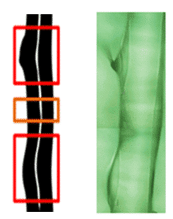
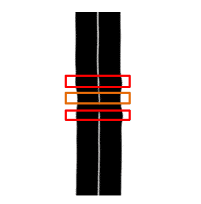
The ZT system has been tested on numerous high speed production areas in the world (e.g. draw towers). The following images were taken of real defects in lines at production speeds ranging from several hundred to several thousand meters per minute.
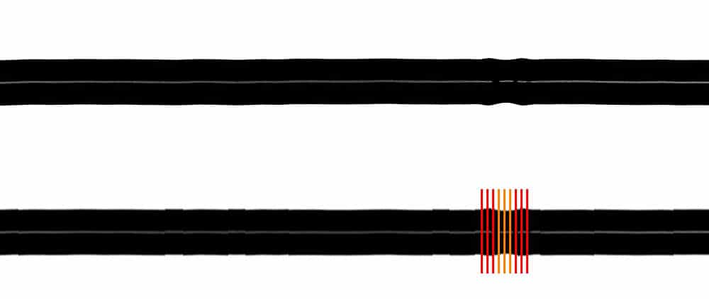
Figure 1 shows a saved defect image from the ZT system compared to a microscope image of the same defect.
Figure 2 shows a sample image of a diameter defect.
Conclusions
With the high speed ZT system, diameter is accurately measured and recorded, along with diameter defect information and defect images. This functionality provides several benefits.
- Suitability for any type of product
- Ensuring the customer will not get defective products, improving customer relationship and confidence
- Reducing rework and eliminating waste, thereby reducing material and labor costs
- Assisting in internal improvements to production processes to reduce defects
Contact us today if you would like to discuss Taymer’s High Speed Lump, Neck-Down and Diameter Detection technology further.


